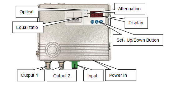
FTTB Optical Receiver is designed as a low power optical receiving device for adapting “Fiber To The Building” (FTTB). This device adopts high sensitive optical phototube, low noise gallium arsenide amplifier chip in preposition and gallium arsenide push-pull amplifier circuit in the last stage which provides a maximum output level over 2×100dBuV.
Additionally, high-precision lightning-protection anti-surge linear power supply, AGC automatic output level control and digital display of optical receiving and RF output level are configured in this fiber receiver. Due to the superior performance of the main material and well-designed circuit, it guarantees the performance index and better reliability of this complete device. Moreover, an optional FTTB network management transponder that supports WEB and HFC network management monitoring and duplexer are added to this device in order to resolve the problem of operator device management or EOC plugin.
ITEM | UNIT | Technical parameters |
Optical Wavelength | nm | 1300~1560 |
Optical Port/Return Loss | /dB | SC or FC/APC(RL≥45) |
Range of input of Optical Power | dBm | -10~+2dBm(receiving -3~-7dBm suggested) |
Frequency Range/Flatness | MHz/dB | 47 or 85~1000/±0.75 |
RF Output Level | dBuV | 2×100/-7dBm |
AGC Feature | dB | -7~+2dBm/nominal output level±1.5 |
C/N | dB | ≥51(-2dBm receiving) |
CTB/CSO | dB | 66/65(when output level at nominal) |
Attenuation/Equalization | dB | 0~15, panel function and WEB monitoring adjustment both supported |
Return Loss of RF port | dB | 47~550MHz≥16,550~1000MHz≥14 |
Operation&Storage Temperature | ℃ | -30~+50/-40~+65 |
Power/Consumption | V/W | 90~250/≤8 |
Outline/Size | mm | 163×125×40, Φ4~Φ5 |

Power In: External Power DC12V In,the screen light '---' turns on when power is connected in, which shows the device is working properly; input level light flicks if no optical signal inputs optical power.
Optical Signal Input: Pigtail connecting in the corresponding optical connector and clean it by over 95% alcohol before connecting; when the optical signal is in, related optical power will be displayed on screen in a unit of dBm. At this time, output level light turns off when CATV carriers wavelength in the optical signal, otherwise, green light flicks.
Output 1/2:If the inside port of standard of branch output is main output, outside port is -20 branch port; inside the port of branch, the output is output 1 and output2.
Set Button: Function Button of this fiber optic product is formed of the set, up and down button, which can complete the setup of channel, EQ and output level. When channel statue lights on and channel number is displayed on the screen after press, channel number can be adjusted based on actual number with up and down button; when EQ statue lights on and EQ value displayed, it can be set based on design and EQ is suggested in 6 to 10 dB properly as a reference as 50MHz level; When output level lights on and output level is displayed, attenuation can be adjusted bigger if the level is thought to be bigger.
1 In case inside, chassis grounding resistance shell must be ground, should be less than 4Ω, The shell feed for electrical grounding resistance must be grounded, alexandrine, also requires cable, for electrical outside shell and the machine shell in the same position, pick up the utility power supply must be first chassis grounding later power supply.
2 Fiber or stern line input and output of this device by TUOLIMA, a reliable fiber optic accessories supplier, must reserve a certain length of cable, lest too tight cause failure.
3 RF distribution when using only 1 as an output signal, another one Ω must be grafted in 75 road port false load.
4 when light power and the design value is an error, should check whether adaptation in optical link connector optical power value displayed, optical power differ + 0.1 dB is normal.
5 the machine according to the energy-saving design, fixed button screen closed, press any key to turn on.
Certification | |||
Checker | J8 | DATE | |
Related Products